close
Choose Your Site
Global
Social Media

Views: 0 Author: Site Editor Publish Time: 2026-10-20 Origin: Site


Optical domes protect sensors by acting as a physical barrier while keeping light able to pass through. These curved parts keep sensitive optics and electronics away from harsh environmental conditions. Temperature extremes, moisture, dust and debris, impact, and chemical exposure all threaten imaging systems. A dome keeps the imaging path working under rain, sand and dust erosion. It also supports imaging in dusty industrial plants and imaging on marine platforms. Reliable protection depends on material, geometry, and coating choices. The same dome must hold imaging quality through thermal cycling and imaging at night. Engineers weigh imaging needs against mechanical loads. This guidance explains the protection mechanisms and the selection factors behind effective optical domes in harsh environments.
Optical domes work as a clear shield. They keep sensors safe from dust, water, and hits.
Pick the right material for each setting. Sapphire resists scratches, and ZnSe handles heat.
Coatings like DLC make the dome last longer. They guard against chemicals and wear.
Test the domes in real-world settings. This makes sure they work in very hot and cold temperatures and under high pressure.
Pick the dome that fits the job. Marine, industrial, and aerospace settings each need their own design.
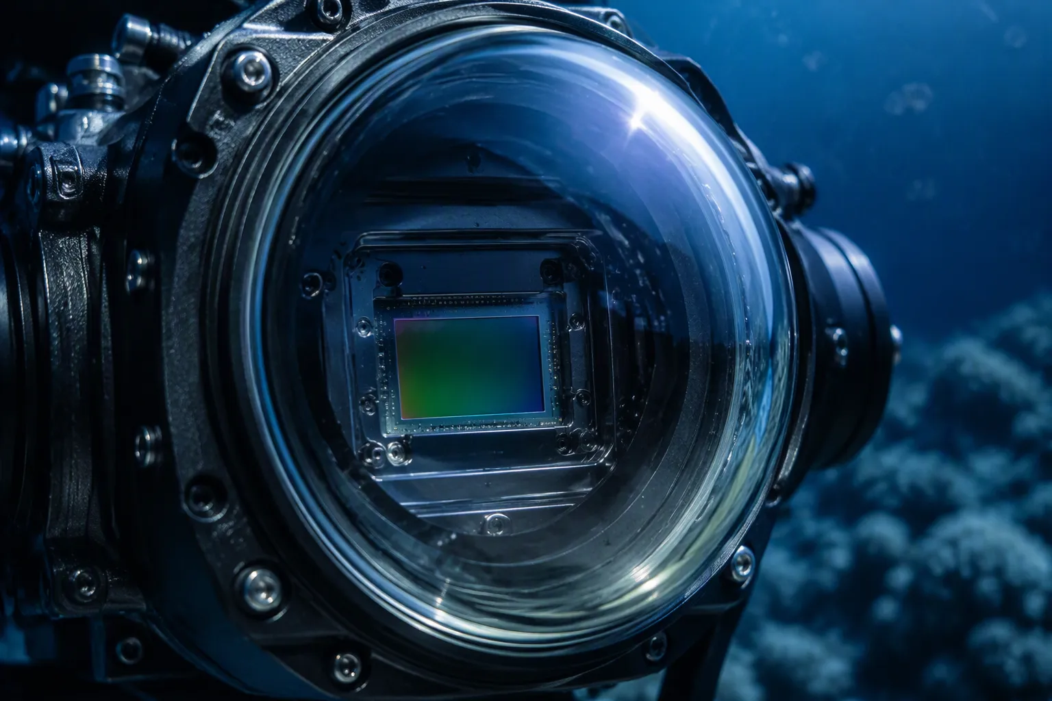
An optical dome is a curved part with two parallel surfaces. It physically separates sensitive optics and electronics from the environment around them. At the same time, it lets light pass along the imaging, sensing, or illumination path. This dual role defines the barrier principle: the dome gives protection without blocking the optical path.
The curved shape matters here. Curved dome surfaces cut surface reflections and boost optical efficiency compared to flat windows, especially at wide angles of incidence. In underwater imaging, the curved surface reduces distortion and aberration caused by the sudden refractive-index change between water and air. That keeps image clarity. Dome curvature controls field of view, distortion, and image sharpness, so each design balances these factors for its application.
A flat window offers a useful contrast. It limits the field of view, especially at the edges, and shows higher aberrations when thick. A dome gives a wide field of view suited to multi-directional sensing, with minimal chromatic and spherical aberrations. It also spreads pressure evenly, so a thinner design can suffice, and it weighs less as a result. For imaging that must hold quality across a broad scene, the curved form earns its place.
Manufacturers place optical domes over cameras, detectors, and electro-optical sensors. The dome acts as a transparent enclosure in high-pressure settings, such as deep-sea cameras, aircraft navigation, and surveillance equipment. It shields lenses and detectors from scratches and abrasion while keeping the imaging path clear. In this way, the optical protective window supports both mechanical protection and optical performance.
Substrate choice shapes that role. UV-grade fused silica tolerates high pressure, which suits underwater use. BK7 offers exceptional chemical stability and good visible transmission. Acrylic remains robust with lower light scatter. Each option fits a different balance of imaging demand and environmental protection.
The optical protective window also manages thermal risk. Heat from high-intensity light sources and electrical components can expand the dome structure. Refractive index shifts with temperature in some infrared materials, and focal shift can follow. Thermally conductive substrates, heat dissipation pathways, and diamond-like carbon coatings help limit these effects. Integrated temperature sensors and feedback control support stable imaging under load.
Designers treat the optical protective window as part of the sensor system, not an add-on. Its geometry, material, and coating decide how well the imaging chain performs. A well-matched optical protective window preserves the protection of optical systems while keeping the imaging path efficient. That is the core value of optical domes in harsh settings.
Band-optics builds its Hemispherical Optical Component & Dome around seven substrate families: sapphire, silicon, SCHOTT N-BK7, ZnSe, ZnS, CaF2, and MgF2. Each one covers a different part of the spectrum and meets a different set of mechanical demands. Sapphire transmits from roughly 0.15 to 5.5 µm, covers UV through mid-IR, and reaches Mohs 9 hardness. That hardness makes it a leading optical window material for scratch-prone imaging on fast platforms. SCHOTT N-BK7 handles visible and near-IR imaging at low cost. Silicon suits the 1.2–8 µm band and brings excellent thermal conductivity for high-heat imaging. ZnSe spans 3–16 µm for LWIR imaging, while ZnS covers visible and infrared together for shared-aperture systems. CaF2 reaches from vacuum UV to about 10 µm, and MgF2 transmits 2–7.5 µm with high flexural strength.
Material | Usable Band | Best Fit |
|---|---|---|
Sapphire | ~0.15–5.5 µm | Abrasion-heavy imaging, UV to mid-IR |
Silicon | ~1.2–8 µm | High-heat IR imaging |
SCHOTT N-BK7 | Visible–NIR | Cost-sensitive visible imaging |
ZnSe | ~3–16 µm | LWIR imaging |
ZnS | Visible + IR | Multi-sensor apertures |
CaF2 | ~0.13–10 µm | Broadband UV–IR work |
MgF2 | ~2–7.5 µm | Domes needing flexural strength |
No single optical window material is the best choice everywhere. The operating wavelength sets the first filter, and the environment sets the second. A marine imaging dome faces salt spray and impact, so sapphire's inert chemistry and hardness fit well. An industrial LWIR camera faces heat and dust, where ZnSe transmission and silicon thermal conductivity each play a role. Aerospace imaging often needs one aperture for visible and IR, which points to ZnS.
Grade, thickness, and coating shift the usable band. UV-grade sapphire removes absorption near 200 nm that standard grade shows. Thicker domes absorb more light, so transmission falls with thickness. An optical protective window specification therefore follows the operating wavelength and the environment together, not the material name alone.
A protective window design must balance curvature, wall thickness, clear aperture, concentricity, and mounting features. Each choice affects both image quality and mechanical strength. Band-optics offers custom windows built from your drawings. Diameters range from about 3 to 180 mm, and thicknesses range from 1 to 20 mm. Dimensional tolerance reaches ±0.05 mm. Surface figure options go from λ to λ/10 at 632.8 nm, and surface quality comes in 80-50 or 60-40 scratch-dig. These ranges let the design fit a specific housing.
Mounting features should be part of the design process from the start. A dome must fit its housing precisely and keep a controlled relationship with the internal optics. Concentricity and critical datums guide that fit. Wall thickness also affects thermal behavior. A thicker wall resists pressure, but it absorbs more light and shifts thermal effects inside the assembly. Engineers weigh these trade-offs during optical window design. The same logic applies to every optical protective window in a sensor system.
Coatings do much of the environmental protection work on optical protective windows. AR coatings cut surface reflection and raise transmission for imaging. BBAR coatings keep that gain across a broad band. HR coatings send light where the system needs it. DLC coatings add hardness, low friction, and chemical stability. Custom coatings handle special bands or exposure conditions.
DLC films have a wide optical bandgap, so they offer high transmittance and low absorption in the infrared spectrum. They also show excellent mechanical and chemical properties, including high hardness, a low friction coefficient, and strong chemical stability.
That profile suits imaging in rugged settings. DLC resists acids, alkalis, and humidity, so environmental durability improves. It also works as a single-layer anti-reflection coating for infrared optics. Coating design for optical protective windows considers wavelength range, incidence angle, and environmental exposure. Moisture, scratch, and chemical concerns each shape the coating choice. Good optical window design pairs the coating with the substrate and the thermal load. This step completes environmental protection for the optical protective window.
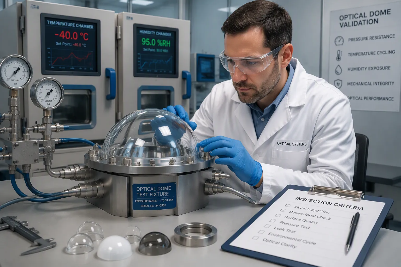
Engineers turn real-world use conditions into optical protective window requirements using six inputs: wavelength, transmission, pressure, temperature, impact, and chemical exposure. Each input helps narrow down the material and coating choices. The table below shows how environmental conditions shape the design.
Environmental Condition | Design Implication for Dome Material and Coating |
|---|---|
Temperature | Plastic domes get brittle and lose clarity when overheated; glass domes made of the wrong material can crack from thermal shock, so the material must match the temperature range. |
Pressure | Flanged glass domes must hold up under high pressures, so the flange material and sealing process must match the load. |
Chemical exposure | The flange material and sealing process must resist damage from the specific chemicals present. |
Radiation | Long exposure to light turns some materials yellow and causes solarization, so materials and coatings that resist radiation are needed. |
Mechanical stress | Impacts, abrasion, and explosions can harm optical and mechanical performance, so tough materials and secure flange seals are important. |
Validation then confirms the design. Environmental qualification puts sample domes through the stated thermal, humidity, and radiation profiles. Pressure and temperature testing proves the flange and seal hold up under load. Inspection criteria — surface quality, figure, and dimensional checks — are agreed with the supplier before production. This sequence keeps optical protective window performance predictable in extreme environments.
Application fit varies by setting. Marine and deep-sea exploration require resistance to water pressure, where flat windows would distort or fail. Salt spray and impact point toward sapphire. Deep-sea exploration also benefits from the curved shape, which spreads pressure evenly. Industrial plants bring sand, dust, and chemical exposure, so materials that are mechanically strong and chemically resistant lead the way. Aerospace and space imaging face temperature swings and UV radiation, so radiation-resistant materials and coatings protect clarity. Each setting balances technical performance, regulatory compliance, and cost in its own way. Marine work relies on pressure certification, industrial work on chemical resistance, and aerospace on thermal and radiation qualification.
A sound selection process follows five steps. Assess application requirements first to avoid over-specification and unnecessary cost. Match the dome to imaging system limits so protection does not degrade optical function. Choose the manufacturing method, since grinding and polishing versus molding affects optical and mechanical resilience. Select material for durability under harsh conditions. Select flange material and sealing process for temperature, pressure, chemical exposure, and radiation. These steps build environmental durability into every optical protective window.
Thermal effects deserve early attention. Heat from light sources and electronics can shift focus in infrared materials, and thermal cycling puts stress on seals. A complete drawing and performance specification — dimensions, tolerances, coatings, quantity, and operating conditions — supports accurate quotation and engineering review. That package lets the supplier confirm optical protective window requirements against real constraints. A well-specified optical protective window preserves both protection and imaging quality. Buyers who document conditions get optical protective windows that fit the environment, not just the drawing.
Optical domes protect sensors through four linked mechanisms. A curved barrier separates optics from dust, moisture, and impact. Durable substrates such as sapphire and ZnSe resist thermal shock, thermal stress, and abrasion. Geometry and coatings manage thermal load and reflection. Validation testing confirms thermal cycling, pressure, and humidity performance.
Selection follows the threat. Material, geometry, coating, and certification must match the extreme environments of each application. A marine dome needs pressure testing. An industrial optical protective window needs chemical resistance. Aerospace work demands thermal qualification. The right dome preserves protection and optical performance together, and it keeps the imaging path clear through thermal swings in a harsh environment.
No. Optical domes cover UV to LWIR as a group, but each optical protective window works in one band. Sapphire, silicon, N-BK7, ZnSe, ZnS, CaF2, and MgF2 fit different imaging jobs. Buyers match optical protective windows to their imaging wavelength and environment.
Sapphire resists scratches for imaging on fast platforms. Silicon pulls heat away under heavy imaging loads. ZnSe handles LWIR work. Each optical protective window balances transmission against toughness. Suppliers machine optical protective windows from drawings, so every optical protective window fits its housing.
AR and BBAR coatings boost transmission for imaging. DLC coatings add hardness and chemical stability for imaging in dusty plants. Coating design for optical protective windows weighs wavelength, angle, and exposure. A coated optical protective window stands up to a wet environment. Buyers specify coatings on optical protective windows early.
Drawings set diameter at 3–180 mm and thickness at 1–20 mm. Tolerance reaches ±0.05 mm. Surface figure runs from λ to λ/10 at 632.8 nm. These limits fit optical protective windows to a housing. Each optical protective window keeps imaging sharp, and optical protective windows keep imaging quality high.
A complete drawing lists dimensions, tolerances, coatings, quantity, and operating conditions. Pressure and temperature needs belong there too. Clear specs help suppliers quote optical protective windows correctly. The right optical protective window keeps imaging clear, and optical protective windows guard imaging hardware.


