close
Choose Your Site
Global
Social Media

Views: 0 Author: Site Editor Publish Time: 2026-10-20 Origin: Site


Four specification categories shape every optical dome decision: optical performance, material and manufacturing method, environmental durability, and flange design and sealing. These categories affect each other. A tighter surface figure may need a different substrate, and a thicker wall may change both optical performance and durability. Your goal is not to maximize every value. Your goal is to match each specification to your application, your wavelength band, and your budget. Each section below explains what a specification means, why it matters, and how to specify it on a drawing. Read them in order, then set your own priorities before you request a quotation.
Pick dome specs that fit your application, wavelength band, and budget instead of making every value as high as possible.
Begin by using your sensor, lens aperture, and field of view to figure out the smallest clear aperture you need.
Pick glass for tough environments and plastic for mild ones. This balances strength and cost.
Show the mounting datums and seal integrity on your drawing. This keeps the optical path clean and lined up.
Put all the requirements on a single drawing, and check with your supplier that they can meet them before you buy.
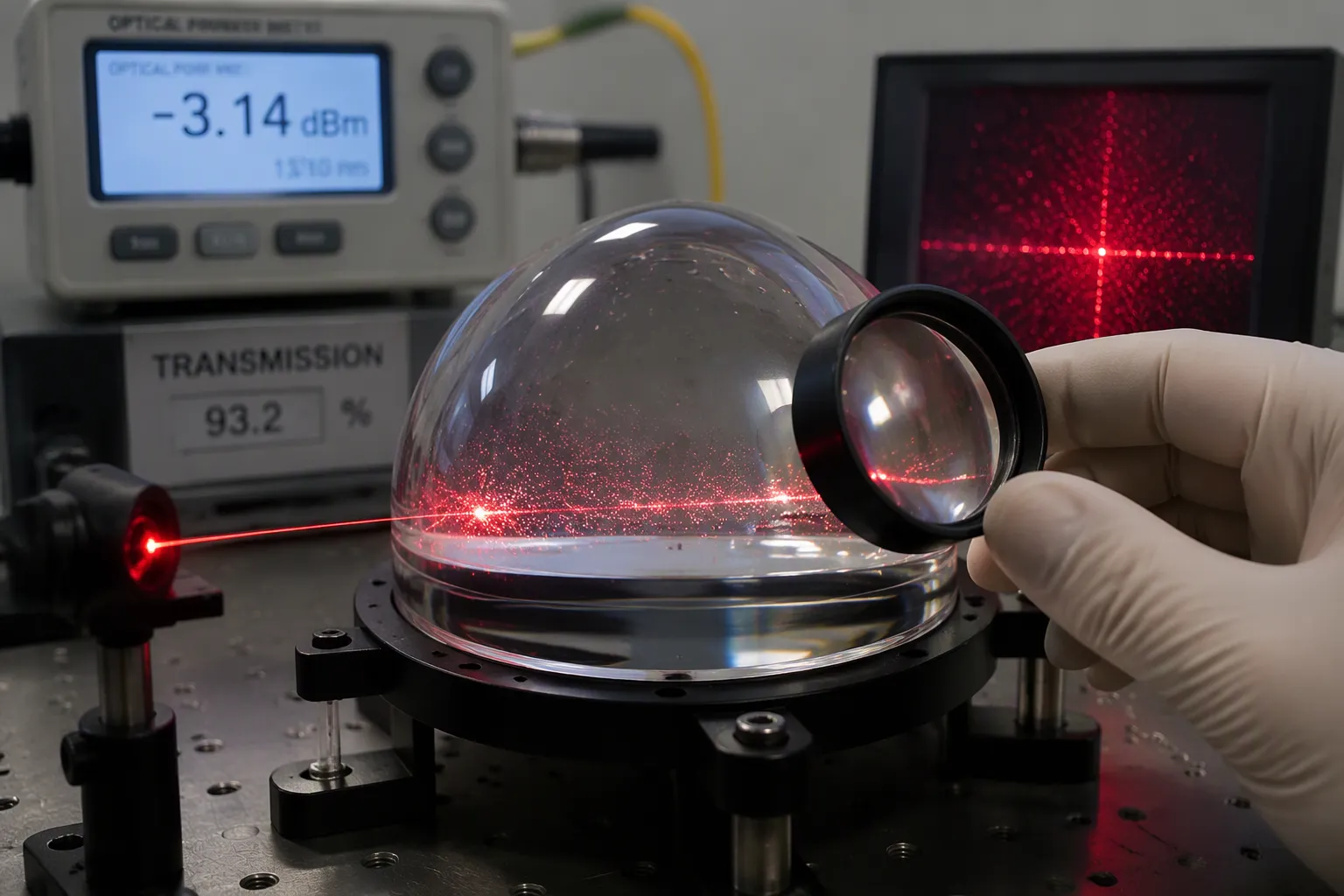
Four problems show up most often in dome optics: distortion, transmission loss, haziness, and speckle. Each one changes what your sensor sees.
Distortion bends straight lines into curves. A dome adds curvature to every ray that passes through it. Your imaging system may then record a scene that does not match the real geometry. You can fix some of this in software, but the fix costs resolution and processing time.
Transmission loss means less light reaches the detector. Every surface reflection and every bit of absorption takes away signal. A weak signal forces longer exposure or higher gain, and both add noise.
Haziness comes from scattering. Bubbles, inclusions, or a rough polish spread light in many directions. The result is a washed-out image with low contrast.
Speckle appears when coherent light, such as laser illumination, reflects off a curved surface. The interference pattern looks like grain. It hides fine detail and makes detection harder.
Good transmission and clarity depend on the substrate, the polish, and the coating working together. Ask for measured transmission across your operating band, not a single number at one wavelength.
Surface figure describes how closely the dome surface matches its designed shape. Band Optics offers figure options from lambda to lambda/10 at 632.8 nm, subject to engineering review. Published ranges also list 1L, 1/2L, and 1/4L depending on size.
Do not mix up surface figure with transmitted wavefront performance. Figure measures the surface itself. Wavefront error measures the light after it passes through the whole dome, including both surfaces, the material, and the thickness variation. A dome with excellent figure can still deliver a poor wavefront if the wall thickness varies. Ask your supplier which one the inspection report covers.
Scratch-dig is a separate acceptance criterion. It grades cosmetic defects by scratch width and dig diameter. Band Optics offers 80-50 and 60-40 scratch-dig. The 60-40 grade is the tighter of the two. Choose it when a scratch could scatter light into a sensitive detector. Choose 80-50 when the dome mainly provides protection.
A near-zero wavefront error target sounds attractive, but it may not fit every budget or geometry. Match the target to your sensor. A protective dome over a wide-field camera rarely needs the same figure as a precision imaging channel.
Band Optics specifies surface figure and surface quality per drawing. The team also confirms capability for the specific geometry and aperture, because a value achievable on a small flat part may not transfer to a large curved shell.
Begin sizing with the sensor, not the dome. Figure out your detector size, your lens aperture, and the field of view your application needs. These three values set the smallest clear aperture the optical dome must provide. A dome that is too small cuts off the light cone and makes the image edges darker.
Work backward from the scene to the part. Trace the widest ray bundle your imaging system needs to capture. Then check that the dome's clear aperture covers that bundle at every pointing angle. The clear aperture is the usable optical zone, so keep mounting features and flange material outside it.
Wall thickness affects two things at once: optical performance and mechanical durability. A thicker wall stands up better to impact and pressure. It also adds weight and can shift the optical path. Thickness uniformity matters just as much. Poor dome geometry, such as non-uniform wall thickness, causes real defects:
Astigmatism
Coma distortions
Resolution loss at the image periphery
These errors hurt camera systems that depend on sharp detail across the full frame. Specify wall thickness and thickness uniformity together on your drawing, and state where each one is measured.
Band Optics makes its Hemispherical Optical Component & Dome in diameters of roughly 3–180 mm and thicknesses of 1–20 mm. Use this range as a sizing reference. Check that your chosen diameter and wall thickness fall inside it before you finalize the design.
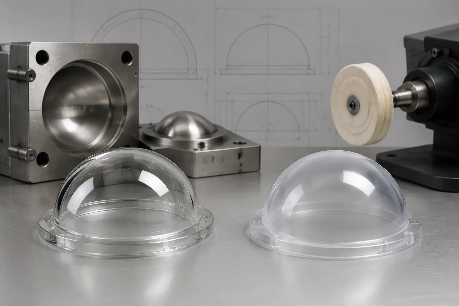
Your first material choice sets the limit for everything else. Glass and plastic each fit different jobs, so compare them on the features that matter to your system.
Attribute | Glass Domes | Acrylic (Plastic) Domes |
|---|---|---|
Durability | Excellent | Impact-resistant but generally less durable |
Scratch resistance | High | Lower than glass |
Chemical resistance | Excellent | Stable but below glass |
Thermal stability | High | Lower |
Cost | Cost-effective for many uses | More affordable |
Molded glass domes, including optical glass domes with flanges, give you better optical clarity and durability. Plastic works for lower-cost or less demanding uses. Acrylic lets up to 92% of visible light through with haze under 1%, and it never breaks into sharp pieces. A glass dome design wins when heat, chemicals, or abrasion are involved. A flanged camera optical glass dome also keeps its shape and clarity over years of outdoor use. Pick plastic to save weight and money, and pick high-quality glass when the dome must survive a harsh environment.
The manufacturing method shapes clarity, cost, and achievable tolerances all at once.
Method | Optical Clarity | Cost | Precision |
|---|---|---|---|
Ground and polished | High precision surface | Expensive and time-consuming | Precise |
Press-molded | May show mold marks and distortion | Lower | Not specified |
Slump-molded | Superior surface quality vs. ground | Lower | Not specified |
Ground and polished domes give you the tightest surfaces, and they cost the most. Press-molding saves money, but mold marks and distortion can lower optical clarity. Slump-molding offers better surface quality than grinding at a lower cost. Match the method to the job: imaging channels need ground surfaces, while protective covers can use molded ones.
Band Optics works with seven substrates: sapphire, silicon, SCHOTT N-BK7, ZnSe, ZnS, CaF2, and MgF2. Material selection and coating both follow your operating band. SCHOTT N-BK7 transmits well from roughly 350 nm to 2 µm and costs little, which suits visible optics. ZnSe stays transparent from about 0.6 µm to 16 µm and serves CO2 laser work. ZnS holds transmission better than germanium during thermal spikes, so it fits thermal cameras and external windows. Sapphire is chemically inert and extremely hard at Mohs 9, ideal for abrasion-facing surfaces. Fluoride crystals such as CaF2 and MgF2 are optically superb but soft and sensitive to thermal shock.
No single material and coating combination covers UV through LWIR. Selection follows operating wavelength, transmission, thickness, and coating. A flanged molded camera glass domes quote for a visible camera will not serve a mid-wave infrared sensor. State your band first, then let the substrate follow.
Durability begins with three kinds of stress: radiation, thermal cycling, and mechanical load. Over time, radiation can darken some glasses and slowly reduce transmission. Thermal cycling makes the dome expand and contract. If the dome and housing do not match, the seal or the shell can crack. Mechanical stress comes from impact, pressure differences, and abrasion.
Material choice is your best defense against all three. Sapphire resists abrasion and thermal shock well. Fluoride crystals such as CaF2 and MgF2 transmit light very well but handle thermal shock poorly. That makes them a good fit for protected, stable settings. ZnS keeps its transmission better than germanium during thermal spikes. Match the substrate to the stress your optical domes will really face. Then confirm the coating can survive the same conditions.
Sapphire is the go-to choice when sand erosion is a worry. Its Mohs 9 hardness resists sand scouring, erosion, and repeated cleaning. A sapphire dome works well in a sandy UAV environment, where grit hits the surface at speed. Wall thickness is not fixed, though. Engineers set it based on the unsupported aperture, pressure difference, mounting design, and a safety factor.
Specification | Sapphire Capability |
|---|---|
Hardness | Mohs 9 |
Scratch-dig | 60/40 down to 10/5 |
Surface flatness | Up to λ/10 |
Environmental resistance | Salt fog, abrasion, high pressure, thermal shock |
Infrared domes follow the same logic for IR systems. The substrate must pass the operating band and survive the platform. Install any dome in a clean, controlled environment. Dust and debris on the surface scatter light and hurt optical quality, even on a hard sapphire shell.
A flange turns a curved shell into a part you can mount. Flange geometry sets how the dome sits in your housing. The mounting datums define the surfaces that control position. Concentricity ties the dome's optical axis to those datums. If you get these wrong, the internal optics no longer line up with the dome.
Picture a flanged camera optical glass dome bolted to a camera body. If the flange face is not square to the optical axis, the dome tilts. The image shifts, and edge resolution drops. If the flange bore is off-center, the clear aperture no longer covers the full field of view. You then lose light at the edges of every frame.
Specify your datums clearly on the drawing. Name the flange face, the pilot diameter, and the axis that matters. State concentricity as a value tied to those features. Band Optics checks mounting dimensions, concentricity, and critical datums from your drawing, so the flange matches your housing rather than the other way around.
The seal between the housing and the glass dome keeps out water, dust, and salt fog. Flange sealing fails in two common ways: a poor surface finish on the flange face, or a gasket that cannot handle thermal cycling. Either one lets moisture reach the internal optics.
Good flange seal integrity protects more than the hardware. A clean, dry interior keeps optical integrity intact. Contamination on the inner surface scatters light, which adds haziness and speckle. A leaking seal also fogs the dome, and that fog cuts transmission. High-quality flanged optical domes reduce distortion, speckle, haziness, and transmission loss because they keep the optical path clean and stable.
Band Optics reviews seal surfaces and mounting features against your drawing. Share your ingress requirements, your gasket design, and your operating conditions. The team then confirms the flange geometry that supports a reliable seal. Well-made flanged optical glass domes and other optical glass domes protect the optics and hold alignment over the life of the system.
Begin with what your application actually needs, not a list of the highest possible values. Ask four questions in order:
Does the dome mainly protect the sensor, or is it part of the imaging path?
Which wavelength band must it pass?
What environment will it face?
What budget can the program carry?
Over-specifying costs money and gains nothing. A dome built beyond what your imaging system can resolve adds cost without adding detail. Match each value to the system's real limits. A near-zero wavefront error target rarely helps a wide-field camera, and a protective cover does not need imaging-grade polish.
Manufacturing method and material carry the same trade-off. Ground and polished surfaces give precision at higher cost and longer lead time. Molded options cost less. Plastic saves money in mild conditions, while optical glass domes hold clarity and durability in harsh ones. Flanged optical domes add mounting and sealing decisions to the same balance. Set seal choices by temperature, pressure, chemical exposure, and radiation. A tailored seal works reliably without extra cost. Run this selection against the full optical camera dome systems you plan to build, including camera systems and their processing limits.
Band Optics builds its Hemispherical Optical Component & Dome from your drawing. That lets you define curvature, clear aperture, wall thickness, coatings, and inspection criteria together, so the optical dome fits your housing and your sensor at the same time. One document carries every requirement, and nothing gets lost between separate specifications.
Some capability combinations need engineering confirmation. A λ/10 figure or 1 arcsec parallelism on applicable features depends on material, size, geometry, and measurement aperture. Treat these as options to verify, not catalog certainties. A complete drawing and performance specification yields the most accurate quotation, and it shortens the review before production.
Four specification categories drive every optical dome decision: optical performance, material and manufacturing method, environmental durability, and flange design and sealing. No single value wins on its own. Picking a dome is a balancing act, not a checklist of maximums. A tighter figure or a harder substrate adds cost, and your system may never see the benefit.
Define your application priorities first. Then specify optical, material, environmental, and flange requirements in that order. Write down every value on one drawing, including tolerances and inspection criteria. Check each capability with your supplier before you buy. A short engineering review now stops a costly mismatch later.
No. The seven substrates cover UV to LWIR as a product family, not as a single part. Each dome is chosen for its operating wavelength, transmission target, thickness, and coating. State your band first, then let the substrate and coating follow.
Send your drawing, material preference or operating wavelength, dimensions, optical tolerances, coating requirements, quantity, and inspection criteria. Add pressure, temperature, and environmental qualification needs. A complete drawing and performance specification gives you the most accurate quotation.
No. Band Optics offers figure options from lambda to lambda/10 at 632.8 nm, subject to engineering review. Material, size, geometry, and measurement aperture all affect the result. Confirm the value for your specific design before you finalize the drawing.
No. Parallelism down to 1 arcsec applies only to applicable features after engineering evaluation. It is not a general specification for concentric dome surfaces. Name the features you mean on the drawing so inspection matches your intent.
Band Optics offers 80-50 and 60-40 scratch-dig. Choose 60-40 when a scratch could scatter light into a sensitive detector. Choose 80-50 when the dome mainly provides protection. State the grade on the drawing next to your figure requirement.


