close
Choose Your Site
Global
Social Media

Views: 0 Author: Site Editor Publish Time: 2026-10-20 Origin: Site


Optical aberrations describe a simple failure: light from one object point passes through a dome and fails to converge to a single image point. The result appears as blur, color fringing, reduced contrast, and distortion.
Why do optical aberrations appear so easily in curved domes? Curvature bends incoming rays at different angles across the aperture, and each wavelength responds differently to the substrate. This article splits the problem into chromatic aberrations, driven by wavelength, and monochromatic aberrations, driven by geometry. Each family pairs with practical correction methods. Correction starts with identifying which error dominates in any given dome design.
The curve of a dome bends light rays in an uneven way, which causes blur and color fringing.
Chromatic aberrations come from light bending differently by wavelength; fix them with material choice and achromatic doublets.
Monochromatic aberrations come from the shape of the surface. You can fix them by using aspheric elements and designing the inner surface.
Pick the correction method that fits the main error and the operating band. This helps you design a dome that works well.
Balance the difficulty of fixing errors with cost and schedule so you don't overengineer.
Optical aberrations are mistakes that keep an image from forming perfectly. Lens shape, refraction, and diffraction all play a part. Light from one object point enters the dome and does not come together at a single point. The image spreads out instead of focusing sharply.
A dome curves in two directions at once. A flat window bends rays the same way across its whole surface. A curved dome bends rays at different angles depending on where they hit. This variation creates optical aberrations more easily than a flat window does. The visible results include blur, color fringing, reduced contrast, and distortion. Each effect comes from rays that miss their intended focal point.
A conformal dome follows the outer mold line of a platform. This shape lowers aerodynamic drag and radar signature. It also creates large conformal dome optical aberrations. The aberration caused by the conformal features of the dome grows quickly because the surface moves away from a simple spherical form. Ray paths through the steep flanks diverge strongly from the paraxial path.
Pupil size makes one error in particular worse. Spherical aberration grows as the pupil gets bigger, because marginal rays focus at a different point than paraxial rays. A larger aperture catches more marginal rays and spreads the focus further. Correcting conformal dome optical aberrations therefore requires attention to aperture size early in the design. Designers who understand how curvature and pupil size drive these errors can plan correction before fabrication begins.
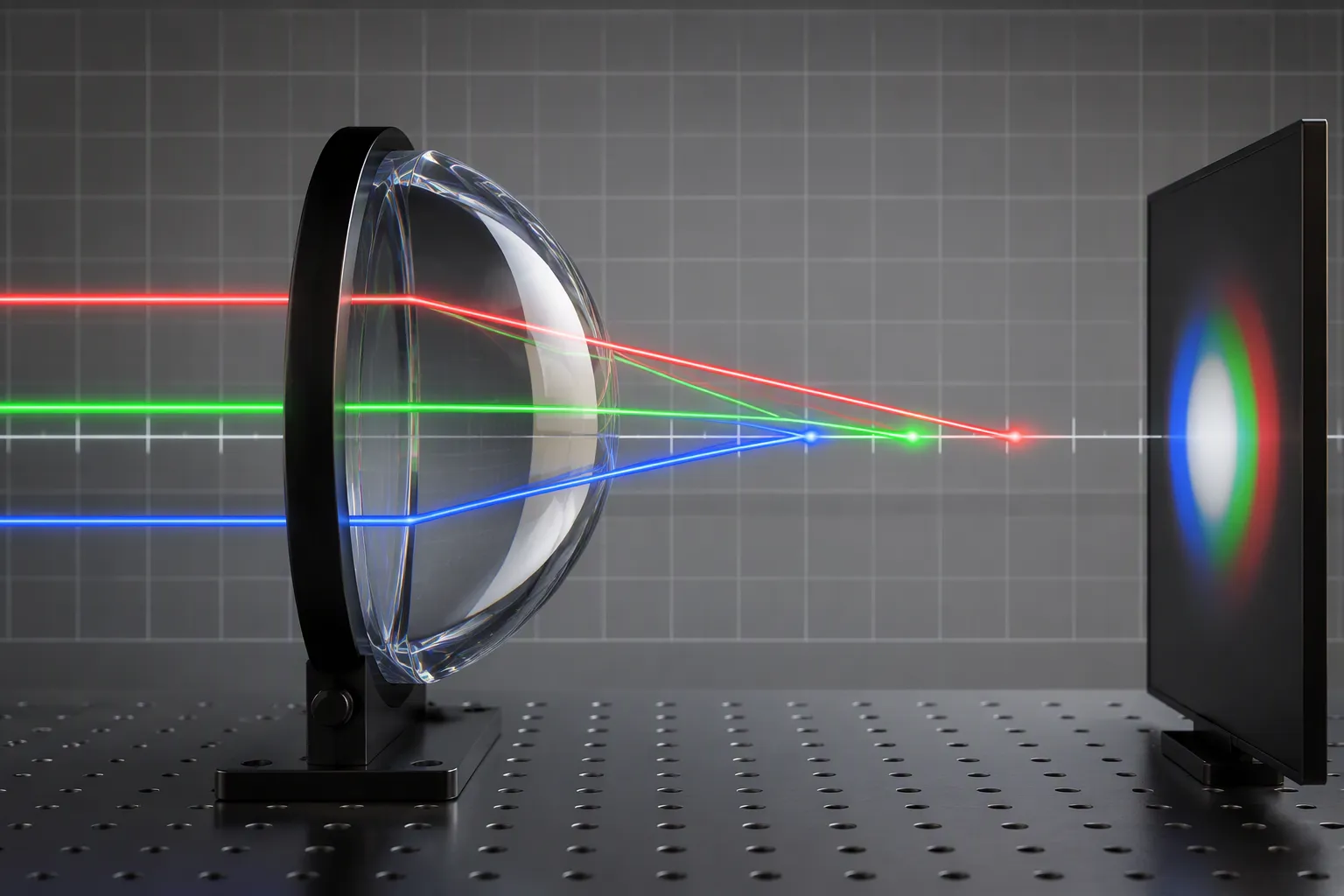
A dome material bends each wavelength by a different amount. This happens because of dispersion: the refractive index of any optical material changes with wavelength. Sapphire, ZnSe, CaF2, and N-BK7 each have their own dispersion curve. No material avoids this effect. The curve is just different, and the dome design must account for it. Chromatic aberrations appear when these wavelength-dependent bends push different colors toward different focal points.
Axial chromatic aberration is a focus shift along the optical axis. Blue light focuses at one distance. Red light focuses at another. The image plane can satisfy only one color at a time, so the others blur. Designers also call this error longitudinal axial chromatic aberration. The size of axial chromatic aberration depends on the dispersion of the material and the power of the dome surface.
A dome with strong curvature shows more axial chromatic aberration than a weak one. The same rule applies across materials. A high-dispersion material spreads the focal positions of the colors further apart. Axial chromatic aberrations therefore need early attention in any dome design that must image across a broad spectrum.
Lateral chromatic aberration is a magnification difference across the field. Each wavelength forms its image at a slightly different scale. The center of the field may stay sharp while the edges show color fringing. Lateral chromatic aberration grows toward the field edge, so wide-field dome systems notice it first.
The two errors often appear together. Axial chromatic error blurs the whole field. Lateral chromatic error smears color outward from the axis. A designer must separate the two before choosing a fix. Correcting for axial color does not automatically remove lateral chromatic error, and the reverse is also true.
Three practical tools address chromatic aberrations in domes.
Achromatic doublet pairing: two elements of different dispersion cancel each other's color spread. An achromatic doublet works well behind the dome, where it corrects leftover color without changing the dome shape.
Wavelength-specific material selection: the material should match the operating band. A designer picks sapphire, ZnSe, CaF2, or N-BK7 according to where the system works, not by habit.
Coating bands matched to the spectrum: AR and BBAR coatings tuned to the operating wavelengths control transmission and reduce stray color effects.
Correcting for lateral color usually needs a different lever than correcting for axial color. A field lens or a second achromatic doublet near the focal plane often handles lateral chromatic error. Correcting for axial color leans on the doublet pair itself. A dome design that combines material choice with a well-placed achromatic doublet controls both errors at once.
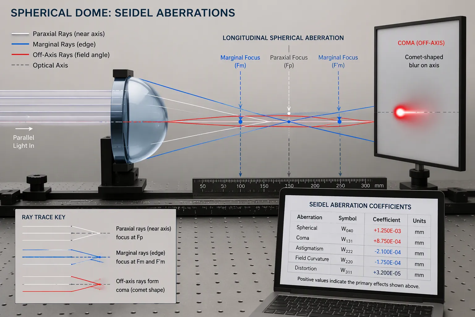
Monochromatic aberrations show up even when the light is just one wavelength. The shape of the lens causes monochromatic aberrations, not dispersion. The Seidel aberrations list five geometric errors: spherical aberration, coma, astigmatism, field curvature, and distortion. Each Seidel aberrations term describes one way rays miss the image point. Seidel aberrations order these errors by power of field angle.
Spherical aberration splits the focus along the axis. Marginal rays cross at a different point than paraxial rays. That gap is longitudinal spherical aberration, and it gets wider as the pupil grows. A bigger pupil lets in more marginal rays, so spherical aberration grows. Correcting for spherical aberration means reshaping elements or adding an aspheric surface. Coma makes off-axis blur shaped like a comet tail. Correcting for coma usually happens together with spherical aberration work, since both respond to element shape. Designers correct spherical aberration and coma by building lens elements of various shapes. Spherical aberration remains the main on-axis error in fast dome systems. A designer measures spherical aberration first, then balances coma against it. Left alone, spherical aberration softens the whole field center. Residual spherical aberration then sets the final blur budget. A ray trace shows the spread directly. The designer compares marginal and paraxial crossings on the plot.
Astigmatism makes two focal lines instead of one point. The sagittal and tangential foci sit at different depths. Correcting for astigmatism needs compensating elements or a tilted corrector. Field curvature bends the image surface away from a flat detector. Petzval field curvature is the built-in part, set by element powers and indices. A dome adds petzval curvature of its own, and that petzval curvature pulls best focus inward. Correcting for field curvature uses a field flattener near the focal plane. Petzval curvature interacts with astigmatism, so both need a joint review. Seidel aberrations theory separates petzval curvature from the astigmatic term. Designers track petzval curvature early, because strong dome curvature raises petzval curvature fast. Field curvature and petzval curvature differ in origin. Field curvature depends on stop position, while petzval curvature does not. Field curvature therefore changes when a stop moves. A flat detector shows field curvature at the edge first. Petzval field curvature sets the baseline sag. Petzval field curvature stays fixed once powers are set. A test target with spokes and radial lines reveals the two depths quickly.
Inner-surface design gives another lever against petzval curvature. Shaping the inner surface offsets petzval curvature before any corrector enters the stack. Additive manufacturing supports this work. Higher-resolution 3D printers build non-distorted element arrays directly on curved surfaces. Radial arc slots drawn directly on the sphere keep radial periodicity equal to the planar unit cell. Optimized fused filament fabrication parameters plus copper electroplating hold dimensional distortion low and conductivity high. Mixed-element arrays with varying dimensions from center to edge reduce edge effects. The approach suits curved apertures where planar arrays would deform.
Distortion moves image position without blurring it. Barrel distortion pulls corners inward, and barrel distortion appears in wide-field domes. Pincushion distortion pushes corners outward, and pincushion distortion follows over-correction. Correcting for distortion relies on stop placement and inner-surface shaping. Barrel distortion and pincushion distortion can share one field. A designer checks barrel distortion at the edge and barrel distortion again after each corrector change.
Band Optics Technology started in 2008 and holds ISO 9001:2015 certification. The company offers its Hemispherical Optical Component & Dome as a drawing-based option for dome design that accounts for aberrations. The platform supports dynamic lenses with Chebyshev polynomial surfaces, inner-surface dome design, aspheric and compensating elements, and material selection across sapphire, silicon, N-BK7, ZnSe, ZnS, CaF2, and MgF2. These choices cover UV through LWIR bands. A designer can therefore match the substrate and coating to the operating spectrum. This avoids forcing one material to cover every band.
Material | Spectral Range | Typical Application | Coating Strategy |
|---|---|---|---|
CaF2 / MgF2 | 0.15–7 µm | IR spectrometers, UV-IR dual-spectrum equipment | Custom AR coating matched to UV/MWIR/LWIR/CO2 wavelength |
ZnSe / ZnS | 0.5–22 µm | Multispectral night vision, 10.6 µm CO2 laser | Multi-band IR AR coating |
Si | 1–7 µm | IR laser ranging sensor paths | Band-matched AR coating |
The Hemispherical Optical Component & Dome supports 3–180 mm diameter, 1–20 mm thickness, ±0.05 mm tolerance, surface figure from λ to λ/10 at 632.8 nm, 80-50 or 60-40 scratch-dig, and AR, BBAR, HR, and DLC coatings. Surface figure is not the same as transmitted wavefront performance, and every combination needs engineering confirmation. Inner-surface shaping offsets petzval curvature before any corrector enters the stack. This step matters when correcting conformal dome optical aberrations. The steep flanks push field curvature inward fast.
Each correction fits a different application. Medical imaging systems benefit from CaF2 and MgF2 domes with custom AR coatings. Here, low dispersion supports color correction across UV and MWIR bands. Laser systems favor ZnSe and ZnS domes with multi-band IR AR coatings for CO2 laser work at 10.6 µm. Semiconductor inspection leans on silicon domes with band-matched AR coatings for IR laser ranging paths. Aerospace platforms need inner-surface design and aspheric compensating elements. Conformal shapes drive the strongest aberrations and demand the most correction.
A designer should match the correction to the dominant error and the operating band. Material choice handles chromatic error. Inner-surface and aspheric work handle monochromatic error. Chebyshev dynamic lenses add flexibility when the field or aperture changes. This layered approach keeps correction complexity aligned with the application.
Dome curvature causes two types of aberrations. Chromatic errors come from the substrate bending ech wavelength differently. Monochromatic errors come from the surface shape, and spherical aberration grows fastest as the pupil gets wider.
Each cause has its own correction tools. Material choice and coating bands take care of color. Inner-surface design offsets field curvature. Aspheric and compensating elements reshape rays to control spherical aberration and coma. Chebyshev dynamic lenses add flexibility when the field changes. Each tool fits where its error is strongest.
Correction complexity should match the application. A designer who weighs spherical aberration against cost and schedule builds a dome that works well without overengineering. That balance defines good dome design.
A flat window bends every ray by the same amount. A dome curves in two directions, so rays hit at different angles across the aperture. That variation spreads the focus and causes blur, color fringing, reduced contrast, and distortion. Conformal shapes make the effect worse because their steep flanks differ strongly from a spherical form.
You should not assume that one material and coating combination covers the whole range. Sapphire, silicon, N-BK7, ZnSe, ZnS, CaF2, and MgF2 each work for different bands. A designer picks the substrate and coating for the actual operating wavelength, transmission target, and thickness.
The biggest error decides the tool. Material choice and coating bands fix chromatic error. Inner-surface design offsets field curvature. Aspheric and compensating elements control spherical aberration and coma. Chebyshev dynamic lenses add flexibility when the field or aperture changes. Matching the tool to the strongest error keeps complexity under control.
No. Surface figure describes the polished surface, not the wavefront that passes through the dome. Material homogeneity, thickness, and geometry also shape the transmitted wavefront. Every combination of figure, size, and material needs engineering confirmation before a designer treats the number as a system guarantee.
A complete drawing helps most. The supplier needs diameter, height, inner and outer curvature, wall thickness, clear aperture, mounting features, optical tolerances, coating bands, quantity, and inspection criteria. Operating conditions such as temperature, pressure, and environmental exposure also belong in the request.


