close
Choose Your Site
Global
Social Media

Views: 0 Author: Site Editor Publish Time: 2026-10-20 Origin: Site


Optical domes protect imaging optics from the world around them. They guard against dust, moisture, and impact without making optical performance worse. Manufacturing optical domes is much harder than making flat windows. Two curved surfaces must work together, and every tolerance affects the final image.
This guide covers the full sequence in order: design, material selection, forming, grinding and polishing, coating, inspection, and delivery. Each stage includes practical techniques and quality checkpoints. Engineers, technicians, and hobbyists can follow these steps to build domes for high-performance imaging systems. Precision at every stage of manufacturing optical domes, not just final inspection, decides whether a dome meets its specification.
Plan the dome with care: figure out the optical needs and shape first, so you don't have to redo costly work later.
Pick the right material for your wavelength band. This keeps light passing through clearly and makes the dome last longer.
Keep stress under control during forming by using annealing and by controlling the process settings. This helps prevent distortion and shape drift.
Use exact grinding and polishing methods like MRF to get the surface figure and finish you need.
Check and pack with care: test how the optic works and use cleanroom packaging to protect the dome.
Every optical manufacturing project starts with a design. This stage sets all the tolerances that come later, so engineers first plan how the optic will be made. A clear plan here stops costly rework later in the process.
The design team begins by listing what the system must do. They write down the operating wavelength band, the required transmission level, and the acceptable image quality. They also note the environment the dome will face, like pressure, temperature, and abrasion. These requirements guide the mechanical and optical design together, since a dome must survive its surroundings while still passing light cleanly.
A complete requirement list also says how inspectors will check the part. Surface figure, scratch-dig, and coating performance all need agreed test methods before production starts. This early agreement keeps the precision of the final part measurable.
The drawing then turns those requirements into dome geometry. Engineers define the inner and outer curvature, the dome diameter, the height, and the clear aperture. They also set the wall thickness, the wall thickness uniformity, the concentricity, and the mounting datums. Each value affects how the dome fits its housing and how well it images.
Curvature choices carry real optical consequences:
Curvature/Design Specification | Impact on Performance |
|---|---|
Convex outer surface with concave inner surface, uniform thickness (monocentric shell) | Inner and outer radii stay parallel, which minimizes aberrations and preserves structural integrity |
Parallel inner and outer surfaces | Cuts refraction variations compared with flat windows, giving clearer imaging |
Spreads pressure evenly, raising resistance to high-pressure environments |
The radius of curvature therefore links optical performance to mechanical strength. Band-optics evaluates its Hemispherical Optical Component & Dome from a customer drawing. That drawing covers diameter (approximately 3–180 mm), thickness (1–20 mm), curvature, and inspection criteria. This drawing-based approach lets the dome design match the actual system rather than a fixed catalog size.
An optical dome lens works with certain materials. Each material gives the best mix of strength and light passage for a certain use. The right pick protects the system and keeps the light path clear.
Band-optics offers seven base material choices for its Hemispherical Optical Component & Dome. Each one fits a different part of the spectrum, and each one has its own strengths.
Material | Best-suited band(s) | Key notes |
|---|---|---|
Sapphire | UV from about 150 nm, visible, IR to about 5 µm | Strong and scratch-resistant, with hardness second only to diamond |
Silicon | NIR and MWIR (3–5 µm) | Common NIR material, with responsivity from 400–1100 nm; more heat-resistant than germanium |
SCHOTT N-BK7 | Visible, also UV and NIR | Excellent transmission for windows and lenses |
ZnSe | Visible to about 8–10 µm, MWIR, LWIR | IR-transparent, covers visible through MWIR |
ZnS | Visible to about 8–10 µm, MWIR | IR-transparent, covers visible through MWIR |
CaF2 | UV, visible, IR | Low refractive index reduces the need for AR coatings; versatile from excimer lasers to thermal imaging |
MgF2 | UV through MWIR (0.1–7.0 µm) | Low cost, but thermally sensitive and needs special handling |
This range lets a designer match the dome material to the job. A visible-band imager and a long-wave thermal sensor almost never use the same base material.
No single material and coatings combination covers the whole UV-to-LWIR range. Oxide compounds stay transparent only below about 7 µm. Past that point, only fluorides, IIB-VIA compounds such as ZnS and ZnSe, and germanium still work. So the choice must follow the operating wavelength, the transmission requirement, the thickness, and the coating.
Fluoride layers bring their own limits. They tend to soak up water, which makes multi-layer coating production harder. They also show low packing density and tensile stress during deposition. Fluoride layers do not work with germanium surfaces, so a binding layer must be added. These factors shape the final design for high ir transmission and reliable lwir transmission. A dome material picked for thermal and ir surveillance platforms must weigh transmission efficiency against these coating realities. Careful manufacturing and precision in this step keep the optical path clear.
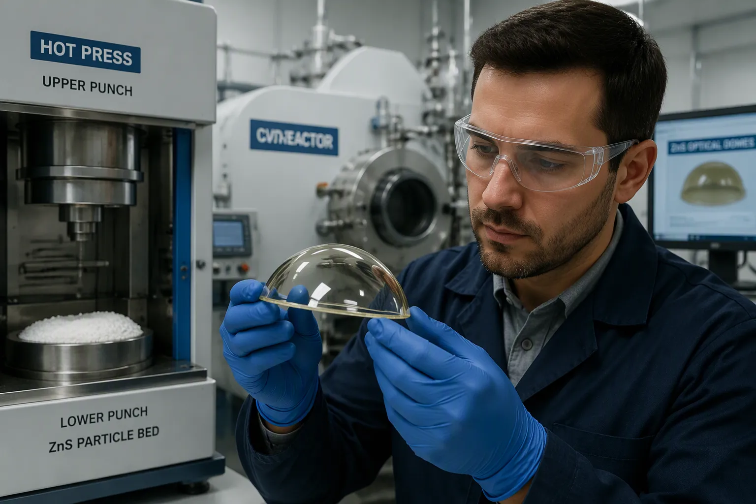
Forming is where making optical domes differs most from making flat windows. A flat window needs two parallel surfaces, and grinding can flatten them. A dome needs those same two surfaces curved, and the curve must hold its shape through every later step. Curved surfaces do not work with the simple tooling that flat work allows, so the choice of method matters more here than anywhere else in the sequence. The forming method also decides how much material later stages must remove and how much stress the part carries forward.
Infrared ZnS shells offer a useful case study, because two routes compete for the same job. Chemical vapor deposition (CVD) grows the material slowly and yields good quality. Cold isostatic pressing (CIP) followed by hot-pressing sintering reaches comparable quality on a much shorter cycle. Both routes produce a curved shell that later grinding and polishing can finish.
Attribute | CVD | CIP + hot-pressing sintering |
|---|---|---|
Quality | Good | Comparable to CVD |
Production period | Long | Much shorter |
Cost | High | Lower |
Productivity | Low | Improved without sacrificing quality |
Pressure uniformity | — | Uniform via flowable inert particles |
IR uniformity and yield | — | Uniform properties, high yield |
The CIP route runs in three stages. First, ZnS powders form a curved green body under cold isostatic pressure. Second, hot pressing sinters that body, with pressure transferred through inert particles for even distribution and the curved shape controlled by a lower punch head. Third, the finished ceramic emerges with uniform infrared properties and high yield.
CVD remains a strong fit where its quality matters most. A polished, uncoated CVD ZnS shell transmits 70–75% in the LWIR, limited by Fresnel reflection losses. An AR coating pushes that above 97%. Homogeneity better than 5×10⁻⁵ supports diffraction-limited imaging. Where a program needs fast turnaround and lower cost, CIP earns the nod. Where the established CVD process suits the specification, it stays in play. Each method serves a different balance of cycle time, cost, and specification.
In optical dome lens manufacturing, forming leaves leftover stress inside the material. That stress causes two problems. It creates stress birefringence, which distorts transmitted light. It also lets the shape drift after the part leaves the press, so the geometry no longer matches the drawing.
Annealing fixes both. A controlled heat cycle lets the material relax before it cools, and slow cooling stops new stress from locking in. Parameter control matters just as much. Pressing pressure, temperature, dwell time, and cooling rate all shape the final stress state. Uniform pressure distribution, such as the inert-particle transfer used in CIP, keeps stress from building up in one region. Engineers record these values for each run, so a shift in stress behavior shows up before parts fail.
A finished optical dome lens that skips this discipline may pass a visual check and still fail later. Stress birefringence shows up in polarization-sensitive systems. Shape drift shows up at final inspection, when the curvature has moved outside tolerance. Treating annealing and parameter control as part of forming, rather than an optional extra, protects the precision built into the design.
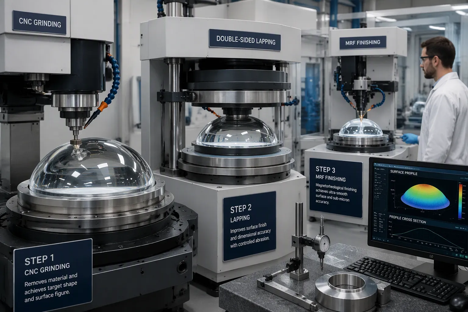
Grinding and polishing are the main steps in making optical domes. These steps turn a formed shell into a finished optical surface. It is very important to control certain manufacturing settings at this stage. Even small changes in tool pressure, feed rate, or slurry condition can change the final shape and surface quality.
Rough grinding removes most of the extra material and brings the part close to its final shape. CNC grinding moves a controlled tool across the curved surface. The machine follows the programmed curve and leaves an even layer of material for later steps. Double-sided lapping then works on both surfaces at the same time. This method makes the wall thickness more even and keeps the inner and outer curves lined up. Together, these processes get the dome close to its final shape before any fine work starts. A well-controlled grind leaves enough material for polishing and prevents deep damage below the surface.
Fine polishing gives the final shape and surface finish. Band-optics uses high-speed polishing and MRF polishing as part of its advanced polishing and shaping technologies. High-speed polishing speeds up work on curved surfaces. MRF polishing uses a special fluid that responds to magnets to remove material in a controlled way. The table below shows what this kind of process can do.
Capability | Typical Specification |
|---|---|
Form convergence (MRF) | 5–10x improvement per iteration |
Surface irregularity (MRF) | λ/30–λ/40 PV (metrology dependent) |
Micro-roughness | <1 nm RMS |
Ultra-low roughness | 0.1–0.2 nm RMS (material dependent) |
MRF head sizes | 10 mm – 150 mm |
Supported geometries | Flats, spheres, aspheres, freeforms |
Production volume | Prototype to high volume |
These methods support the surface figure options offered for the optical dome lens: λ, λ/4, λ/6, λ/8, and λ/10 at 632.8 nm. Surface quality options include 80-50 or 60-40 scratch-dig. Surface figure depends on the material, size, shape, and inspection evaluation. High-precision dome manufacturing therefore depends on matching the polishing method to the part. A large sapphire dome and a small CaF2 dome need different tool paths and different removal rates. Apex precision on the curved surface requires steady control of the polishing head. The optical dome lens that leaves this stage carries the shape and finish that later coatings must build on.
A plain dome surface bounces light away from the sensor. Optical coatings fix this problem and add protection. Band-optics offers anti-reflection coatings, broadband anti-reflection coatings, high-reflection coatings, diamond-like carbon films, and custom designs. Each type does a different job, and each one needs a clear specification before deposition starts.
Coating Type | Design Considerations |
|---|---|
AR (Antireflection) | Specify target wavelength range, incidence angles, and required reflection/transmission levels |
BBAR (Broadband Antireflection) | Define performance across the full required operating band |
HR (High Reflection) | Used where reflective functionality is needed on designated surfaces |
DLC (Diamond-Like Carbon) | Assess protective needs, substrate compatibility, and impact on optical performance |
Custom Coatings | Provide target spectrum, surfaces to be coated, and environmental requirements for review |
Coating design must think about wavelength range, incidence angle, coated surfaces, substrate compatibility, and environmental exposure. Curvature makes this task harder. A spherical surface has local normals that change across the clear aperture, so the angle of incidence shifts from point to point. The coating stack must keep working across that spread.
Coating availability and achievable performance depend on the substrate, geometry, and application; AR, BBAR, HR, DLC, and other custom optical coatings are offered across the dome product family.
Edge work finishes the part before inspection. Technicians add chamfers to the rim to remove sharp edges and lower the risk of chipping during handling and mounting. They also clean up mounting features, so datums and interfaces meet the drawing without burrs or residue.
Cleanliness comes next. A multi-stage precision cleaning process removes dust, polishing residues, fingerprints, and oils from the optical dome lens. Workers do this cleaning in a controlled environment and check particle levels against agreed limits. Visual and optical inspection begins only after cleaning. This order protects the precision built into every earlier stage of manufacturing.
Inspection checks whether the finished dome matches its drawing. A surface figure spec does not show how well light passes through. A part can meet a λ/4 figure and still fail the system's imaging needs. So engineers must agree on inspection methods before production starts. The test setup, the aperture, and the pass/fail rules all belong in that agreement.
Transmitted wavefront testing measures how the whole dome affects light passing through it. This test catches errors that a surface figure check alone cannot see. Both surfaces, the wall thickness, and the material homogeneity all play a part in the result. Teams that plan this test early avoid disputes at delivery.
Dimensional checks cover diameter, height, curvature, wall thickness, and concentricity. Each value must fall inside the drawing tolerance. Parallelism gets separate treatment. Band-optics can evaluate parallelism down to 1 arcsec for applicable features, and the achievable tolerance is 30 arcsec. This limit applies only to features that engineering review approves. It does not apply to concentric dome surfaces.
Surface quality follows optical surface quality standards such as MIL-PRF-13830. Under this standard, the scratch number is a visual comparison grade, not a direct width measurement. The dig number gives the largest allowed dig diameter in units of 0.01 mm.
Grade | Maximum dig | Typical application |
|---|---|---|
60-40 | 0.40 mm | Commercial imaging, protective windows, industrial sensors |
40-20 | 0.20 mm | Precision imaging, spectroscopy, many laser systems |
20-10 | 0.10 mm | High-contrast imaging, focused beams, demanding laser optics |
Acceptance also depends on the number, location, and distribution of defects, not only the largest single flaw. Band-optics holds ISO 9001:2015 certification and supports drawing-defined tolerances and agreed inspection methods. This discipline keeps manufacturing predictable and protects the precision built into every dome.
Packaging protects the work done in every step before it. A finished dome leaves the cleanroom only after it is wrapped with care. Small parts go into cleanroom anti-static PE bags or lens tissue, one by one. Each piece then rests in a custom-cut EVA or PU foam tray. The foam holds each part apart, which stops surface rubbing and collisions. The anti-static bag keeps particles from sticking. Large domes get protective paper between glass surfaces, plus shock-absorbing foam around them, packed in rigid export cartons. All packaging materials stay low-dust and non-abrasive, so they leave no residue and scratch no polished surface.
Cleanroom requirements mandate Class 100 or better environments during critical fabrication steps to minimize particulate contamination.
Labels keep traceability intact. Each package carries a part number, a lot or serial identifier, and the drawing revision. A QC team checks package integrity before shipment. This check confirms the seal stays intact and the contents stay free of contamination. Buyers with cleanroom receiving protocols should tell the supplier at the RFQ stage, so packaging matches their intake rules.
Transit exposes a dome to shock, vibration, and moisture. Shock-absorbing cases soak up that energy before it reaches the optic. Designers pick compliant materials for this job. Silicone gaskets, soft silicone gel, and plastic frames each cushion impact in a different way. Silicones are very flexible and give off very little gas, which suits sensitive optical surfaces. A rigid outer case then adds a second layer of defense against direct impact.
Humidity control matters for hygroscopic materials. Hygroscopic polymer gels can capture and manage moisture in the air, and smart humidity-control systems can capture, release, and self-regulate. Desiccant packs inside a sealed barrier offer a simpler route for most shipments.
Documentation travels with the goods. Inspection records are agreed during the quotation stage, and the purchase specification states which records are required. Categories include dimensional, surface, optical, coating, and material records. The supplier provides them according to the agreed order and quality requirements. This paperwork closes the loop on manufacturing and gives the receiver proof that the dome met its specification.
The seven stages always happen in the same order: design, material selection, forming, grinding and polishing, coating, inspection, and delivery. Each stage passes its result on to the next one.
Precision and quality control at every step decide whether a dome meets its performance specifications. Final inspection alone cannot save a part that formed with locked-in stress or was polished past its tolerance. Manufacturing optical domes rewards early process control, from the first drawing to the last annealing cycle.
Readers should treat each stage as connected to the others. A change in material affects forming, and a change in curvature affects coatings. When you ask for a quote for an optical dome lens, give a complete drawing and performance specification. That one habit leads to better manufacturing decisions from the start.
No. The seven substrates each cover different bands, and no single material and coating combination covers everything. Sapphire works for UV up to about 5 µm, while ZnSe and ZnS reach the LWIR. Designers choose the substrate based on the operating wavelength, transmission target, thickness, and coating.
A complete drawing defines diameter, height, inner and outer curvature, clear aperture, wall thickness, thickness uniformity, concentricity, and mounting datums. It also states optical tolerances, coated surfaces, and inspection criteria. Band-optics checks each dome against that drawing, with diameters from roughly 3 to 180 mm and thicknesses from 1 to 20 mm.
No. Lambda/10 at 632.8 nm is an engineering option. Whether it is available depends on the material, component size, geometry, measurement aperture, and inspection method. Each combination needs technical confirmation before production.
No. Parallelism down to 1 arcsec applies only to features that engineering review approves. It is not a general specification for concentric dome surfaces. Inspectors evaluate it case by case.
A complete drawing and performance specification help the most. Buyers should add material preference or operating wavelength, coating requirements, quantity, inspection criteria, and operating conditions. Pressure, temperature, and environmental qualification details also help guide the review.


